Design and Simulation of a Probe-Fed Patch Antenna Using HFSS
Objective: The primary goal of this project was to design, simulate, and analyze a probe-fed patch antenna using ANSYS HFSS. By examining the antenna’s reflection coefficient (S-parameter) over a range of frequencies, I gained insight into the fundamentals of antenna design and performance.
Procedure Overview: Using HFSS, I modeled a rectangular patch antenna fed by a coaxial probe. The major steps involved setting up the substrate, ground plane, patch, and feed; applying appropriate materials; assigning boundary and excitation conditions; and defining a frequency sweep for simulation.

The antenna was placed on a dielectric substrate (Rogers RT/duroid 5880) with a ground plane beneath it. A coaxial feed, with inner and outer conductors modeled in HFSS, provided the probe connection from the patch to the signal source. Radiation boundaries on the surrounding air box simulated an open environment, ensuring electromagnetic waves could radiate freely. A wave port was defined at the end of the coax to excite the antenna and capture the reflection coefficient.
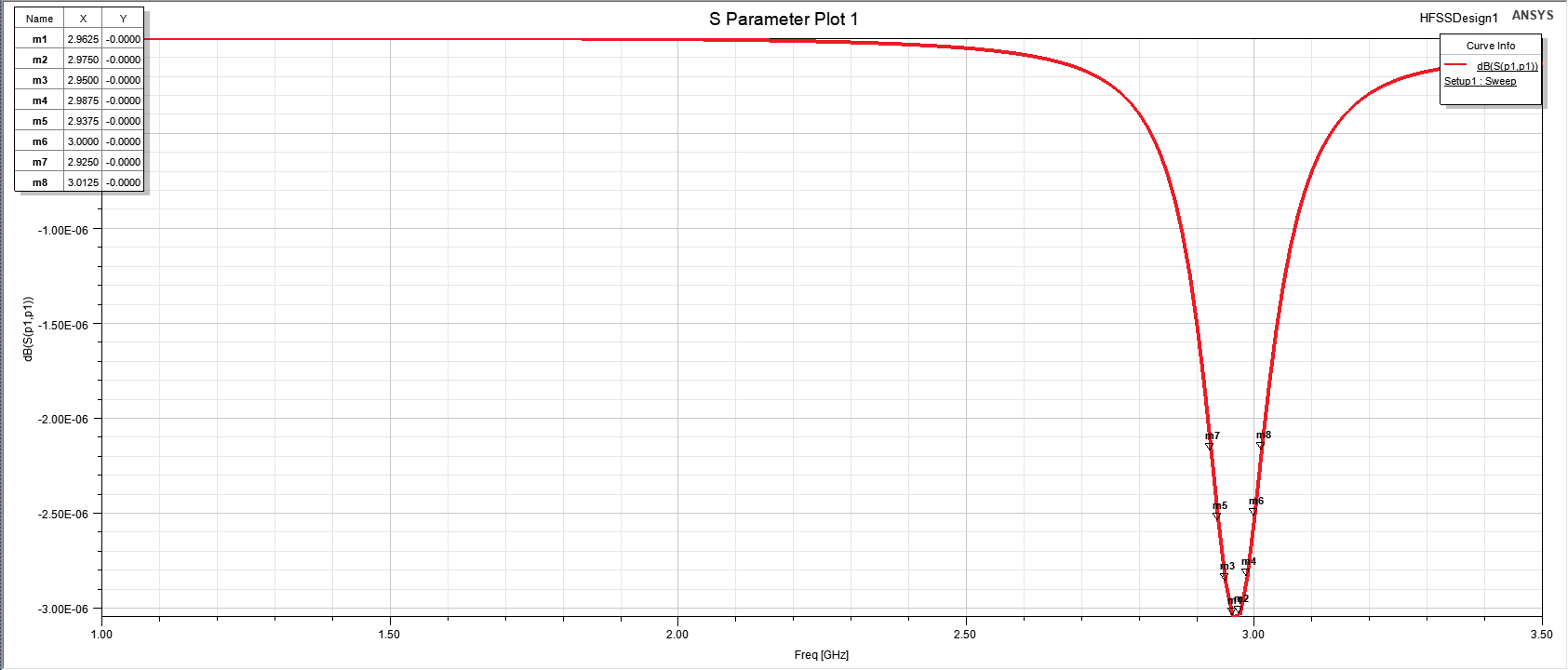
Results: The reflection coefficient plot indicated a primary resonance around 2.95 GHz, where the coefficient reached approximately -3e-6. This suggested strong coupling at that frequency, as expected from the design goals. The low reflection implied the antenna effectively absorbed and radiated energy near this resonant frequency.
Conclusion: This project reinforced the practical considerations of designing a probe-fed patch antenna. Working with HFSS highlighted how parameters like substrate choice, patch dimensions, and feed placement influence overall performance. Observing the S-parameter plots provided a clear indication of the antenna’s operating frequency and how well the design matched the intended resonance.